This section concerns the way that TRANSP handles the evolution of the q profile (and by extension the current profile, poloidal magnetic field and rotational transform). At JET it is most common to read in a q profile as a function of time and simply use this profile, however one can set initial conditions and have TRANSP evolve these profiles via solution of the Poloidal Field Diffusion Equation and this is also sometimes used. When a q profile as a function of time is specified, the PFDE allows the calculation of a resistivity profile, this profile is purely an output and is not used elsewhere in TRANSP. Non-physical values may indicate problems with the input data. As in other sections this section focusses on the settings used at JET, others are available, for more information see the PPPL TRANSP website.
NLMDIF : Set this flag to TRUE in order to have TRANSP solve the 1D poloidal field diffusion equation in order to advance the q profile and
related quantities in time. By default this is done such that the calculated total plasma current matches the input value. It is possible to have TRANSP modify
in order to match the surface loop voltage as well although this is not commonly
used at JET.
NLPCUR : This flag is TRUE by default and indicates the behaviour described above where the total plasma current is a boundary condition on the
solution of the PFDE. When set to FALSE the total current is predicted and a different boundary condition must be used.
NLVSUR : This flag is FALSE by default in which case the surface loop voltage is predicted by the solution of the PFDE. When set to
TRUE the surface loop voltage is used as a boundary condition for the solution of the PFDE. If both NLPCUR and NLVSUR are set to TRUE
the value in the PFDE is adjusted as a function of time in order to
satisfy both constraints. If NLPCUR is FALSE then the plasma composition
is used.
The default configuration is NLPCUR=.T and NLVSUR=.F which is the configuration commonly used at JET. If this configuration is desired, these two flags can
therefore be omitted from the namelist file.
NLQDATA : When NLMDIF=.F set this flag to TRUE in order to use an input q profile as a function of time. This q profile is
input using the QPR trigraph in the TRDAT namelist (PREQPR, EXTQPR). Note that in the default case where the plasma current is also used as a boundary condition,
the q profile in the edge region is modified in order to force a consistent solution. The region where the q profile is modified is set using the variable
XUSEBPB. This sets a value of r/a below which the q profile will remain unchanged.
The following controls allow the user to switch between different schemes for determining the q profile over the course of the run. Be aware that these controls effectively overwrite the
ones in the previous section when set (by default there is no time switching and the previous controls apply). The scheme to be used for determining the q profile in the ith
time interval between times TQMODA(i-1) and TQMODA(i) is set using the controls NQMODA(i)
and NQMODB(i). The following options are commonly used at JET. For information on the others see the PPPL website.:
NQMODA(i)=1 : Use the poloidal field diffusion equation to predictively solve for q in the interval ti-1 to ti (i.e. set
NLMDIF=TRUE for this period. The flag NQMODB then configures the auxillary switches as follows:NQMODB(i)=1 : NLPCUR=TRUE, NLVSUR=FALSE, NLINDUCT=FALSE (Default)NQMODB(i)=2 : NLPCUR=TRUE, NLVSUR=TRUE, NLINDUCT=FALSENQMODB(i)=3 : NLPCUR=FALSE, NLVSUR=TRUE, NLINDUCT=FALSENQMODB(i)=4 : NLPCUR=FALSE, NLVSUR=FALSE, NLINDUCT=TRUENQMODA(i)=4 : Use input q profile data from trigraph QPR i.e. set NLDIF=FALSE and NLQDATA=TRUE:NQMODB(i)=1 : NLPCUR=TRUE (Default)NQMODB(i)=2 : NLPCUR=FALSETAUQMOD : This specifies the transition time over which the q profile is smoothly merged from one scheme to another. The default is 0.025s.
When solving the poloidal field diffusion equation predictively the following boundary conditions are employed:
These quantities allow the calculation of the edge value of the q profile and the slope of the voltage profile at the boundary. Further to this there are the constraints that there is zero poloidal field and zero gradient in the voltage profile at the magnetic axis. In order to solve the PFDE it is also necessary to provide an initial boundary condition. The following switches control how this is set:
NEFLD : This switch controls the method used to initialise the PFDE. If it is set to 3 an analytic form for the voltage profile is used:
V(χ)=V1 + V2 χ2 + α(1-χXPEFLD)2
Where χ is ,
XPEFLD is an exponent which must be set greater than 1.25 (default 2.0) and α is a free parameter.
The constraints above then dictate that the sum V1 + V2 be equal to the surface voltage, this is adjusted to ensure consistency with the input plasma current when NLPCUR=1.0.
Furthermore the value of V2 is determined from the gradient of the voltage profile at the boundary. α is a free parameter and can be fixed in two different ways:
QEFLD = 0.0 sets α=0.0 QEFLD ≠ 0.0 and RQFLD ≠ 0.0 sets the resulting q value
at χ=RQFLD equal to QEFLD.If NEFLD is set equal to 7 the PFDE is initialised using input q profile data.
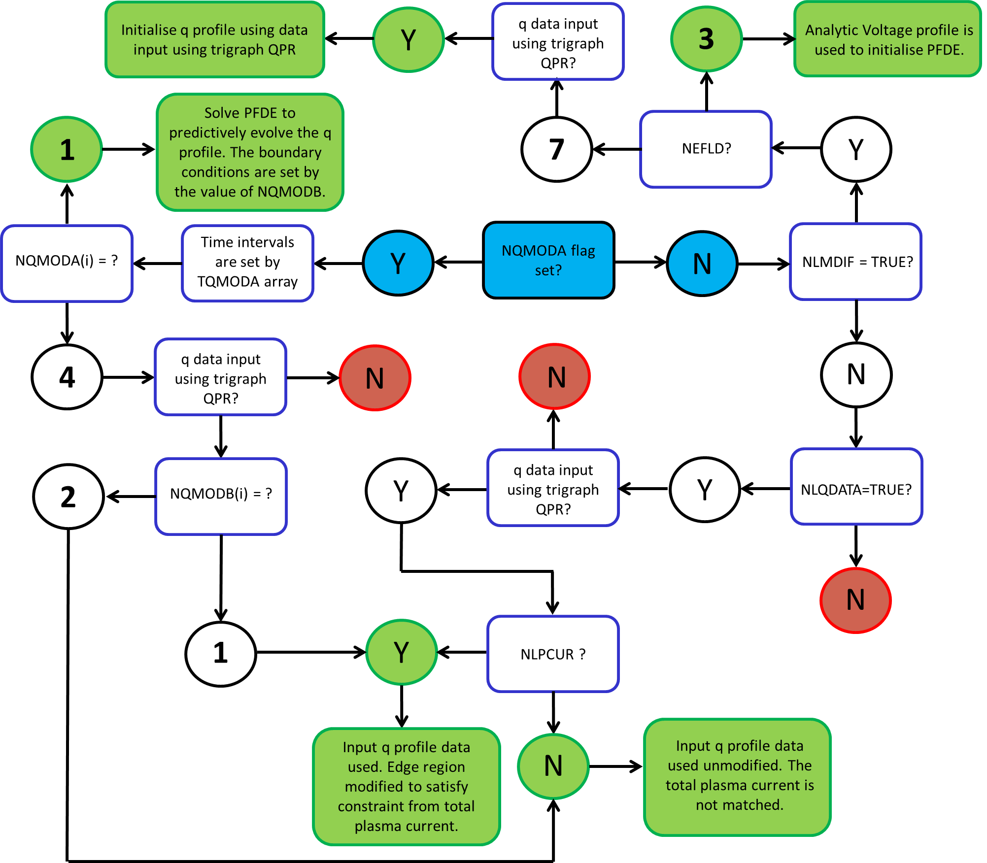
The following flow chart depicts the possible ways of specifying a q profile. The starting location is the blue 'NQMODA flag set?' decision box. If an end location is coloured green it represents a valid run configuration, if it is coloured red it is invalid and will not run successfully.
c.f. NCLASS Controls
Several models are available for calculation of the plasma resisitivity that is used when predictively evolving the current profile. At JET it is common to use NCLASS to calculate
the full generalized geometry neoclassical resistivity. The resistivity calculation is controlled using the following switches:
NLSPIZ : Set to TRUE (default) to use the classical Spitzer resistivity and FALSE for any of the neoclassical models.
At JET it is common to use NCLASS for calculations of the resistivity and so this switch is usually set to FALSE.
NLETAW : Set to TRUE to use NCLASS.
XL1NCETA : This specifies a value of r/a below which the neoclassical resistivity transitions smoothly back to the classical limit as r/a->0.
The default value for this is 0.0 but the PPPL website suggests a value of 0.1 may also be appropriate due to physical reasons for doubting the validity of the neoclassical
calculation on axis.
Other options are available, see the PPPL TRANSP website.
As for the resistivity above, different models can be used to calculate the neoclassical bootstrap current. As above it is common to use NCLASS for this at JET.
NLBOOT : Set to TRUE to include bootstrap currents in the solution of the poloidal field diffusion equation. By default a neoclassical
model based on an aspect ratio approximation is used.
NLBOOTW : If NLBOOT is set to TRUE this can also be set to TRUE to calculate the neoclassical bootstrap currents
using the NCLASS neoclassical code. This is what is commonly done at JET.
XL1NCJBS : This specifies a value of r/a below which the neoclassical bootstrap current transitions smoothly to 0.0 as r/a->0.
The PPPL website recommends that the default value of 0.1 should be the minimum value of this parameter used.
Other options are available, see the PPPL TRANSP website.
Beam driven currents can be included in the solution of the PFDE using the switch NMCURB. The options for this are as follows:
It is common at JET to use setting 3 which utilises the updated neoclassical model.
Additional magnetics data can be read in using the following switches. Note that only one of NLBDIA and NLBPDA can be set.
NLI2PB : Setting this flag to TRUE indicates that data for li/2 + beta(Pol.) should be read in.
The source of this data is specified using PREL2B and EXTL2B.NLBDIA : Setting this flag to TRUE indicates that data for diamagnetic beta(Tor.) should be read in.
The source of this data is specified using PREBDI and EXTBDI.NLBPDA : Setting this flag to TRUE indicates that data for diamagnetic beta(Pol.) should be read in.
The source of this data is specified using PREBDI and EXTBDI.NLDFLX : Setting this flag to TRUE indicates that data for the diamagnetic flux should be read in.
The source of this data is specified using PREDFL and EXTDFL.NLEDIA : Setting this flag to TRUE indicates that data for the diamagnetic energy should be read in.
If the voltage profile changes sign near the center the PFDE solver can fail. to avoid this a minimum voltage can be set using the following two switches:
VLPMIN : Sets a minimum voltage allowed anywhere in the voltage profile.
VLPMML : Sets the minimum voltage allowed as VLPMML*(Surface Voltage).
When using an input q profile it is possible that the calculated resistivity and consequently the ohmic power produced are negative. This is normally indictative of problems with the input data but it can be circumvented by calculating the ohmic power using the classically or neoclassically calculated resistivity. To do this set NMODPOH=2.