The quality of TRANSP results is largely dependent on the effort invested into rigorously preparing the input magnetic equilbria and profiles, and ensuring basic output plasma parameters match the standard consistency measurements. More on the effort to establish a set on standard consistency checks and how to perform these in OMFIT/TRANSP can be found in this presentation, which was done as part of the JET Good Data project led by the Task Force Leaders. This page details the three basic data consistency checks that should be performed after every TRANSP analysis to ensure the quality of a given run. Please note that these three parameters represent the minimum required set, while more checks potentially need to be made, depending on the scenario type, physics aim and Scientific Coordinator comments. Standard set signals are available for both OMFIT and JETDSP - they can be found in the standard sets section and are described below:
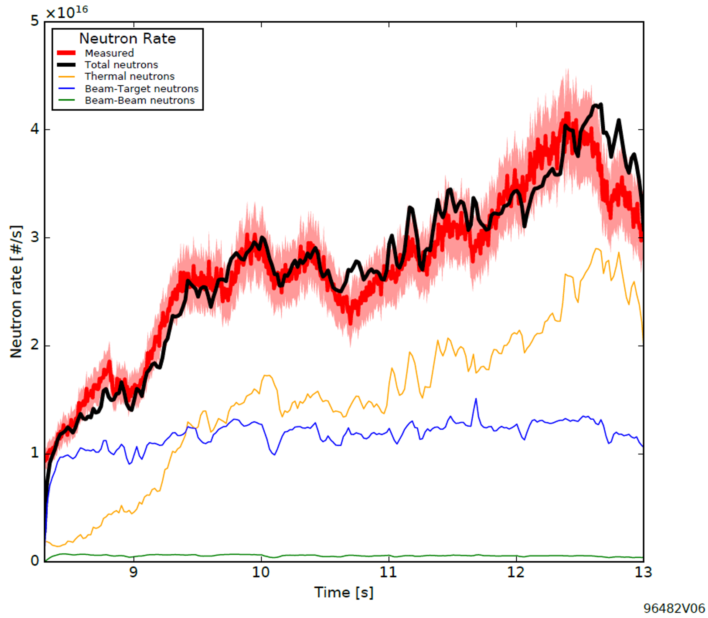
TRANSP calculates the total rate of neutron emission as well as its source components - namely thermal, beam-target and beam-beam fusion. The calculated value can be compared with
the total neutron rate measured by fission chambers, as shown in the figure below. We can generally expect a good match between the measured and calculated neutron rates, which should
match within ~ 10 % (estimated experimental uncertainty). In particular cases, i.e. discharges with lower NBI power and neutron rates of the order of 1.0e15, TRANSP results can
over-predict the measurements by around 20 % to 30 %. The reason for this is currently unknown but studies are ongoing. In such cases we recommend to check if the time-trace
profile shapes agree.
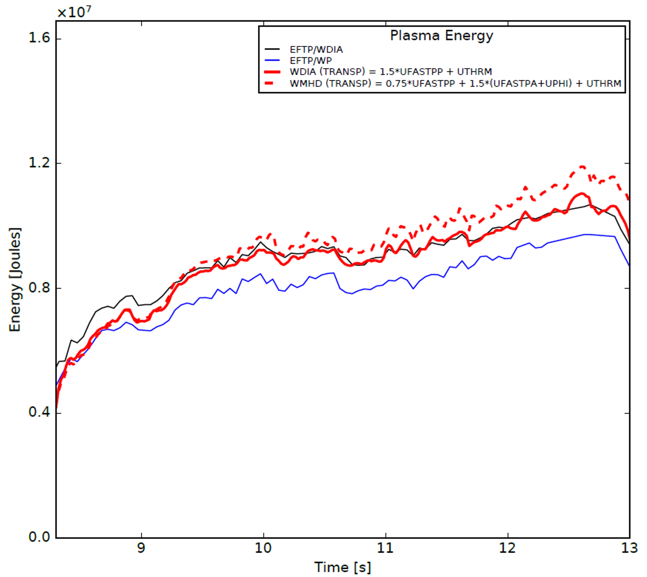
One of the consistency parameters is the diamagnetic energy - this is calculated as part of the equiibrium reconstruction (EFIT) and includes the plasma diamagnetic energy
and the plasma MHD energy. These quantities are not output by TRANSP by default and need to be derived from the the thermal and fast ion energy. For more information on these quantities
and their derivation see this reference or this paper. If you wish to compare EFIT and TRANSP please
take note of the following issue - by default EFIT is run assuming TI=TE and no contribution of fast ions to the total MHD pressure, i.e taking into account only the thermal
contribution stemming from electron kinetic profiles. In contrats TRANSP takes into account both the
meaured TE and TI profiles, as well as the effect of an evolved fast ion species. Ion order to be able to compare the diamagnetic energy stemming from the two different
methodologies, it is often necessary to run a pressure constrained EFIT++ reconstruction using total MHD pressure profiles (TRANSP output quantity 'PTOWB') from TRANSP
as a constraint. You can request such a reconstruction by contacting the EFIT RO at JET, or run one yourself
through the kineticEFITtime module in OMFIT.
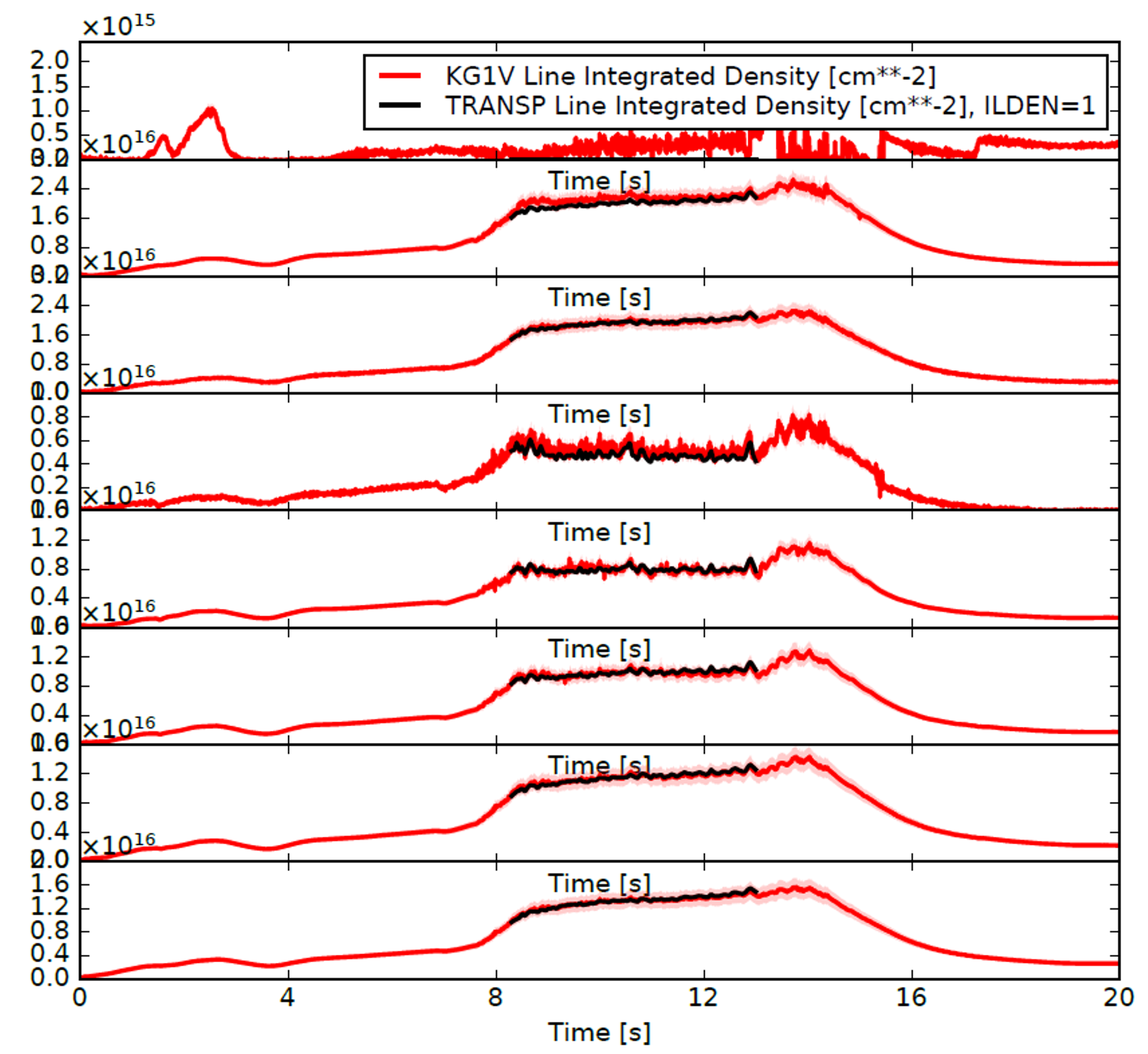
TRANSP contains a synthetic interferometer which models the signals which would be seen by JET's KG1V laser interferometer channels. A direct comparison can be made to the
measured inferformeter data. Agreement here gives confidence in the measured profiles, their fits, and the quality of the equilibrium. Please note that the different KG1 channels correspond
to lines-of-sight over which the density
measurements are integrated. For example the third channel, i.e. LID3, measures the electron density closest to the plasma core. Usually the electron density is fitted to the
HRTS measurements at JET. while these have been shown to give an accurate radial profile shape, the absolute value of the measured electron density is suspected to be too large.
This has been found through comparisons with KG1, which is absolutely calibrated. HRTS NE was found to be around 10 % too large, radially independently, with the discrepancy further depending on TE. This means that in Ohmic
phases of discharges KG1V/LID and HRTX/LID match, but in the heating phases the discrepancy between the two grows. Analyses have been done by EK experts and ROs, and are reported in presentations by
M. Maslov and H. Damm & J. Flanagan.
It is common practice to rescale the input NE Ufiles after comparing against KG1V/LID signals to obtain a match.