This section details the way that the thermal ion species densities and radial flow velocities are determined during the simulation. When only one thermal ion species is present quasi-neutrality and knowledge of ZEff is sufficient to constrain the value of the ion density. The particle balance equation can then be solved to determine the radial flow velocity of the species. In order to do this knowledge of the gas injection and wall recycling is required and various ways are available of providing this which are outlined below. When more than 1 thermal ion species is being simulated additional information is required allowing the separate species densities to be determined. Again TRANSP allows many different ways of doing this. At present it is possible to include up to 7 thermal ion species which must be isotopes of Hydrogen, Helium or Lithium. Please refer to the start of the Plasma Composition section for details of how to specify the thermal ion species being used.
The local form of the particle balance equation has the general form:
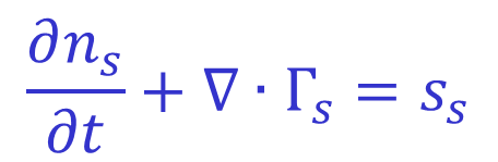
Where
Integrating this over the plasma volume one obtains the following equation for the species populations:
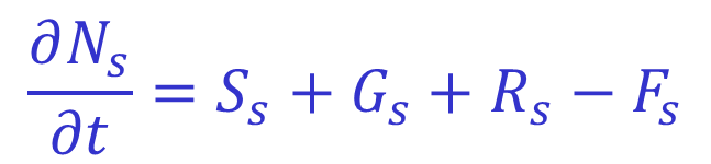
Where
The beam source is determined by the NUBEAM Monte Carlo code. Usually at JET one specifies Gs using input gasflow data from the PPF GASM/MAJR and uses the integrated wall Dα photon flux from EDG7/FLW to determine the recycling source. In the case of a single ion species where the density profile as a function of time is known, this is then sufficient information to solve these equations for the particle flux and radial flow velocity. When more than one species is present similar equations exists for each species and the user must supply futher information to determine how these equations are used in conjunction with quasi-neutrality and ZEff to determine the evolution of the densities and fluxes of the different species present.
The NDEFINE variable may be passed a list of values indicating how the densities for the different thermal ion species are to be determined.
At least one ion species must have this setting. All ion species with this setting will be evolved according to the value of the NMODEL
variable. If only one species is present this is ignored and the species density is determined from quasi-neutrality and ZEff. The allowed values for the NMODEL
variable are (others are defunct):
NMODEL=1 : With this choice of NMODEL a species independent profile shape is used for the densities of all NDEFINE=0 species.
This shape is determined via simultaneous solution of the
quasi-neutrality and ZEff equations for a total thermal ion density profile. Each species is then assumed to have a profile proportional to this shape with a magnitude
given by the initial conditions and the total rate of influx of this species as dictated by the gas flow, recycling, beam sources etc.
NMODEL=4 : While the densities of the individual species are currently unknown, the Z weighted sum of these densities can be determined from quasi-neutrality, ZEff
and knowledge of the other species densities (impurities, species with given input data etc.). A continuity equation for this sum can be formed by summing the continutity equations of the
constituent species:
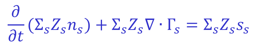
This allows the total 'Z-weighted' flux to be determined which can then be used as a constraint.
When NMODEL=4 is chosen, each species is allowed to evolve independently according to:
in such a way that this total flux constraint is met. In order for this to occur the user must specify the diffusivities D for each of the species. This is done using the variable
NDIFFI as follows:
DIFFUS is 0.0)DE2 [ cm2/s ]
The following switches allow limitations to be placed on the diffusivities used when this method is employed:
DFIMIN: The minimum allowed value of the diffusivity. Input values are constrained to be at least this value. (Default = 0.0)
DFIMAX: The maximum allowed value of the diffusivity. Input values are constrained to be at most this value. (Default = 105)
DLTKIE: This limits the local rate of change of the diffusivity by specifying a maximum amount by which the diffusivity can change within a millisecond.
Having defined the diffusivities one must still define N-1 constraints for the convective velocities VC as we only have the one global flux constraint to begin with.
In order to close the system of equations the user must also specify the relative mobilities of the different species. Effectively this involves specifying the ratios of the convective
velocities for the different species. To do this use the variable VIFAC(i). Note that only the ratios of these values between the different species is
important. The default value is 1.0 for all species.
NOTE : For each species VIFAC(i)>0 is required and for each pair of species i & j VIFAC(i)/VIFAC(j)>0.1 is also required.
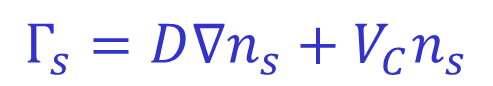
Species with this setting are evolved predictively. Input data for the convective flow velocity or the diffusivity (or both) must be provided for this species. The flux is then considered as a sum of a diffusive and a convective term:
Where
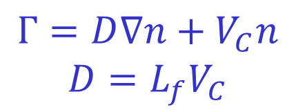
At least one and at most two of the above quantities must be specified via Ufile input. The following combinations are allowed:
| D and VC | These values can be used directly in the equation for the flux. |
| Lf and VC | The lower equation is used to derive a diffusivity from the convective velocity and scale length which is then used in the equation for the flux. |
| VC only | The diffusivity is set to zero in the equation for the particle flux. |
| D only | The convective term VCn is set to zero in the equation for the particle flux. The lower equation is not used. |
Note that the variables DFIMIN and DFIMAX described above also apply to the diffusivities used here.
The Ufile trigraphs used to input transport data for use with this option are summarised in the table below.
| D | VC | Lf | |
| Hydrogen | DFH | VCH | LFH |
| Deuterium | DFD | VCD | LFD |
| Tritium | DFT | VCT | LFT |
| Helium 3 | DF3 | VC3 | LF3 |
| Helium 4 | DF4 | VC4 | LF4 |
| Lithium 6 | DF6 | VC6 | LF6 |
RECYCH(i) : In the absence of input data for the wall recycling, this variable sets the fraction of the outflux which is recycled at the wall
for NDEFINE=1 species. This variable is also used when NRCYOPT=1. See the recycling section for details.
When using NDEFINE=1 an initial condition must be set for the species composition. Use the FRAC variable described below to do this.
If this option is selected the density for this species is set directly either via Ufile input or as a set fraction of the electron density. Density Ufiles can be specified using the following trigraphs:
| Species | Trigraph |
| Hydrogen | NIH |
| Deuterium | NID |
| Tritium | NIT |
| Helium 3 | NI3 |
| Helium 4 | NI4 |
| Lithium 6 | NI6 |
If no Ufile input is provided for a species, its density must be set as a fraction of the electron density using the variable FRAC_NDEFINE2(i) which has a default value of 10-4.
Species for which NDEFINE=0 or NDEFINE=1 require an initial condition specifying the relative concentrations of these species at the initial time. The initial
state of the plasma is set using the following variables:
NG: The initial number of thermal ion species to be used.
FRAC(i): The relative concentration of species i.
Each of the species initialised in this way will have the same shape initial profile proportional to

where the sum is over impurity species and thermal ion species with NDEFINE=2. The magnitude of the resulting profiles will be chosen so as to satisfy the constraints of
quasi-neutrality and composition ZEff.
Neutral beams, gas puffing and pellet injection can all result in species being present in the plasma which were not initially. The variable NGMAX
sets the maximum number of species which can ever be present in the plasma. The variable RHMINM sets the minimum density of any species present in the plasma
as a fraction of the electron density. When a new species is introduced via one of the methods mentioned previously, it is initialised with this density and the densities of the
other species are modified accordingly. It has a default value of 10-12.
NOTE: If a species with index i is present in the plasma then all species from 0 to i-1 must also be present and if they are not TRANSP will initialise them on introduction of species i.
This means that species should be indexed in the order they intend to be introduced into the plasma to stop species being prematurely initialised.
TRANSP does not contain a detailed model of the edge of the plasma and consequently simplifying assumptions must be made when dealing with edge sources. When NRYCOPT≠2
the input gas flow and recycling sources specify total ion fluxes into the plasma due to this source. The profile of the deposition of these ion sources is determined by the neutral
transport code FRANTIC. This calculates the profile of ion sources due to ionisation and charge exchange of neutral particles and this is then renormalised to input fluxes.
In this case FRANTIC considers any neutrals lost from the plasma to be 100% reflected back from the edge. This is a modelling assumption. Note again that TRANSP contains no model
for calculating gas flow ion sources from the original neutral gas flow or for calculating the recycling ion source from diagnostic measurements such as Dα light. It simply
expects an ion source rate due to these sources and the user must perform whatever analysis is required to determine this a priori.
A Ufile detailing the gas injection rate can be input using trigraph GAS. This Ufile is assumed to specify an ion influx due to neutral injection.
If this is not provided the ion influx is taken as 0.0.
If NLRCYC=TRUE the input Ufile can specify the summed gasflow of multiple species. The Z of the species for which this applies
is set using the namelist variable XZRCYC. The input gas flow is then apportioned amongst the species for which Z=XZRCYC
using the variable GFRAC:
Gi = I × GFRACi / Σj GFRACj
Where Gi is the resulting gas flow for species i and I is the input gas flow data. The sum extends over all species with Z=XZRCYC.
If NLRCYC=FALSE or for species not having Z=XZRCYC, gas flow data must be provided via a species specific Ufile
(See Ufiles section below for trigraphs). Z for species i is BACKZ(i).
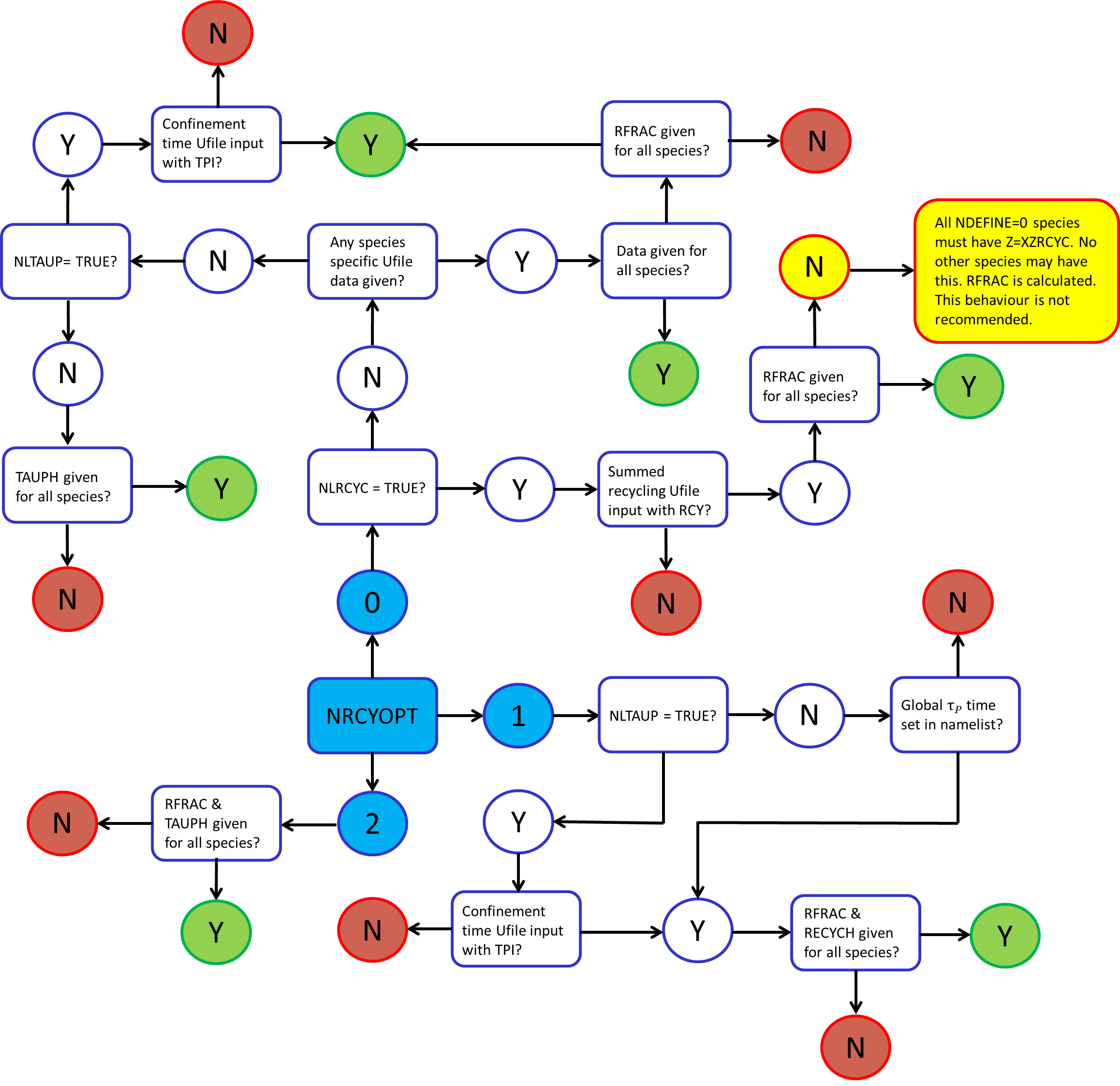
TRANSP allows several methods for specifying the recycling sources of the different thermal species and the impurities. These methods either rely on input data for the particle confinement times or for the actual magnitudes of the recycling sources for one or more species or a mixture of several. In the former case the recycling source can be fixed such that the total species amount and the resulting ion outflux at the edge give the specified particle confinement time. The method used to determine the recycling source is governed by the namelist switch NRCYOPT which is by default set to 0.
In this case two options are available. One can set NLRCYC=TRUE in order to read in a Ufile specifying the total recycling source
summed over all species for which Zi=BACKZ(i)=XZRCYC or one can specify Ufiles containing recycling data for individual species using the
trigraphs listed in the Ufiles section.
In the first case where a summed recycling source is input, the individual species recycling sources are determined using the values of
RFRAC(i) for each of the species as follows:
Ri = I × RFRACi / Σj RFRACj
Where Ri is the resulting recycling source for species i and I is the total recycling source, in this case from input gas flow data.
The sum extends over all species with Z=XZRCYC. Note that
species with Z≠XZRCYC may be given species specific input Ufile data. If this data is absent they too will be assigned a recycling source based on the above
formula and must therefore be given a value of RFRAC. If one is not specified a value is calculated based on the edge densities of the species in the previous timestep.
This behaviour is not recommended. In this instance the summation still only extends over the species included in the summed Ufile data with Z=XZRCYC.
Again, two options are available. One can either input time dependent Ufile data for the particle confinement time by setting NLTAUP=TRUE
and using the trigraph TPI or one can specify a time independent confinement time for each species using the namelist variables TAUPH(i)
and for the impurities with TAUPO. In the former case the recycling source is determined for each species such that:
τ = Ni / Fi
Where Ni is the number of particles of species i and Fi is the outflux at the edge of ion species i. The species with NDEFINE=0 are treated
as a group yielding a total recycling flux for all NDEFINE=0 species. This is then apporioned between the different species using the values of the RFRAC
variable for each species and the same formula as in the preceding section except that the summation now extends over the species for which NDEFINE=0.
Note that if any Ufile recycling data
is passed, then this behaviour is overridden and the recycling sources for species without Ufile data are determined from those with Ufile data using the values of the
RFRAC variables.
This choice selects a model where the total recycling source for each species is a mixture of a prompt recycling term which is a fraction of the ion outflux for that species, and a limiter outgassing contribution which is chosen to match a global particle confinement time which must be provided as input either via a Ufile or directly in the namelist. The resulting recycling source for species i is then:
Ri = Fi × RECYCHi + F0LIM × RFRACi / Σj RFRACj
The first term on the right hand side is the 'prompt' recycling source. Fi is the ion outflux for species i and the namelist entry
RECYCH(i) specifies what fraction of this is recycled. F0LIM is a limiter outgas flux which is chosen to match
the input confinement time. The values of RFRAC(i) specify how this is apportioned between the ion species. The summation is over all ion species.
RFRAC must be specified and be non-negative for each species. RECYCH must be also be specified for each species and satisfy 0<RECYCH<0.95.
No input Ufile data is permitted when using this option. Note that the variable RECYCH is also used to specify the fraction of the ion outflux which is recycled for
species with NDEFINE=1 when no other recycling information is available. See the NDEFINE section above for more information on this.
In this case, thermal neutrals which leave the plasma are not perfectly reflected back into the plasma as in the other cases but are instead lost. Gas flow and recycling sources
set by input data are reduced to accommodate this. A global particle confinement time is calculated as the edge weighted average of the particle confinement times of the different
species as set by the namelist variables TAUPH(i). This is then used to determine a total recycling flux which is apportioned between species based on the values of
RFRAC(i) for the different species. For NDEFINE=1 and NDEFINE=2 species, separate recycling sources may be specified.
NLRCYI : Setting this to true will mean that thermal ion species for which NDEFINE=2 have their recycling source fixed such that their
confinement time is equal to that specified for the NDEFINE=0 species.
NLRCYX : Setting this to true will mean that the impurity species have their recycling source fixed such that their
confinement time is equal to the global particle confinement time for the thermal ion species.
The following trigraphs may be used to input species dependent 1D ufile data for the gas flow and recycling thermal ion sources in units of ions s-1:
| Species | Trigraph |
| Hydrogen (Gas flow) | GFH |
| Deuterium (Gas flow) | GFD |
| Tritium (Gas flow) | GFT |
| Helium 3 (Gas flow) | GF3 |
| Helium 4 (Gas flow) | GF4 |
| Lithium 6 (Gas flow) | GF6 |
| Hydrogen (Recycling) | RCH |
| Deuterium (Recycling) | RCD |
| Tritium (Recycling) | RCT |
| Helium 3 (Recycling) | RC3 |
| Helium 4 (Recycling) | RC4 |
| Lithium 6 (Recycling) | RC6 |
If NLRCYC=TRUE indicating that source data summed over different species is being input then the following data must be provided:
| Source | Trigraph |
| Gas Flow | GAS |
| Recycling | RCY |
This data is divided amongst the thermal species with Z=XZRCYC as described above.
The following flow chart depicts the various recycling options. The starting location is the blue 'NRCYOPT' decision box. If an end location is coloured green it represents a valid run configuration, if it is coloured red it is invalid and will not run successfully.